LNL Logo

Return to How -To Page

Fuseology

The purpose of the fuseology section is to promote a better understanding of both fuses and some of the more common application details. The fuses to be considered are current sensitive devices which are designed as the intentional weak link in the electrical circuit. The function is too provide circuit protection by safely melting under current overload conditions. This brief study will cover some important facts about fuses, selection considerations, and fuse standards.


Fuse Facts

AMBIENT TEMPERATURE: Refers to the temperature of the air immediately surrounding the fuse and is not to be confused with "room temperature". The fuse ambient temperature is appreciably higher in many cases, because it is enclosed (as in a panel mount fuse-holder) or mounted near other heat producing components such as resistors, transformers, etc.

BREAKING CAPACITY:See short circuit rating

CURRENT RATING:The nominal amperage value marked on the fuse. It is established by the manufacturer as a value of current which the fuse can be loaded to based on a controlled set of test conditions. (see DERATING)

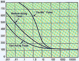
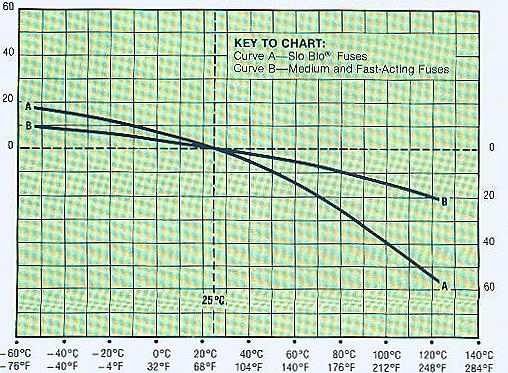
DERATING: For 25 degree C ambient temperatures, it is recommended that fuses be operated at no more than 75% of the nominal current rating established using the controlled test conditions. These test conditions are part of Underwriters Laboratories Standard 198G "Fuses for Supplementary Overcurrent Protection" whose primary objective is to specify common test standards necessary for the continued control of manufactured items intended for protection against fire, etc. Some common variations of these standard include: using fully enclosed fuse holders, higher contact resistances, air movement, transient spikes and changes in connecting cable size (diameter and length). Fuses are essentially temperature sensitive devices and even small variations from the controlled test conditions can greatly effect the predicted life of a fuse when loaded to its its nominal value usually expressed as 100% of rating.

The circuit design engineer should clearly understand that the purpose of these controlled test conditions is to enable fuse manufacturers to maintain unified performance standards for their products and he must account for the variable conditions of his application. To compensate for these variables the circuit design engineer who is designing for trouble free long life fuse protection of his equipment generally loads his fuse not more than 75% of the nominal rated listing by the manufacturer, keeping in mind that overload and short circuit protection must be adequately provided for. The fuses under discussion are temperature sensitive devices whose ratings have been established in a 25 degree C ambient. The fuse temperature generated by the current passing through the fuse increases or decreases with ambient temperature change. The ambient temperature chart in the fuse selection section illustrates the effect that ambient temperature has on the nominal rating of a fuse. Most slo-blo designs use lower melting temperature materials and are, therefore, more sensitive to ambient temperature changes.

DIMENSIONS:The fuses range from small, pico (.095" dia. x .280" body length) up to the 5AG, also commonly known as a "midget" fuse (13/32" dia x 1-1/2" length). As new products were developed throughout the years fuse sizes evolved to fill the various electrical circuit protection needs. The first fuses were simple open wire devices, followed in the 1890's by Edison's enclosure of thin wire in a lamp base to make the first plug fuse. By 1904 Underwriters' Laboratories had established size and rating specifications to meet safety standards. The renewable type fuses and automotive fuses appeared in 1914, and in 1927 Littelfuse started making very low amperage fuses for the budding electronics industry.

The fuse sizes in the chart below began with the early "Automobile Glass" fuses, thus the term "AG". The numbers were applied chronologically as different manufacturers started making a new size "3AG" for example, was the third size placed on the marker. Other non-glass fuse sizes and constructions were determined by functional requirements but they still retained the length or diameter dimensions of the glass fuses. Their description was modified to AB in place of AG, indicating that the outer tube was constructed from Bakelite fibre, ceramic or similar material other than glass. The largest size fuse shown in the chart is the 5AG, or "MIDGET", a name adopted from its use by the electrical industry and the National Electric Code range which normally recognizes fuses of 2" x 9/16" as the smallest standard fuse in use.

All fuses, regardless of size and body material, have a specified current rating, voltage rating, and fusing characteristic. The correct selection of fuses for safe, inexpensive and trouble free circuit protection will only come when these three factors are thoroughly understood.

FUSE SIZES
SIZE DIAMETER LENGTH
1AG 1/4" (0.250") 5/8" (0.625")
2AG - (0.177) - (0.588)
3AG 1/4" (0.250") 1-1/4" (1.25")
4AG 9/32" (0.281") 1-1/4" (1.25")
5AG 13/32" (0.406") 1-1/2" (1.50")
7AG 1/4" (0.250") 7/8" (0.875)
8AG 1/4" (0.250") 1" (1.0")

FUSE CHARACTERISTICS: The Characteristic of a fuse design refers to how rapidly the fuse responds to various current overloads. Fuse characteristics can be classified into three general categories: fast acting, medium acting, or slo-blo. The chart below shows typical time-current curves for the different fusing characteristics. Current rating and characteristic are both needed to define a fuse, since fuses with the same current rating can be represented by considerably different time-current curves. Slo-blo fuses have additional thermal inertia designed in so that the fuses can tolerate some normal initial or start-up overload spike.

INTERRUPTING CAPACITY: See SHORT CIRCUIT RATING.

RESISTANCE: The resistance of a fuse is usually an insignificant part of the total circuit resistance. Since the resistance of fractional amperage fuses can be several ohms. This should be considered when using them in low voltage circuits. Actual values can be obtained from the factory. Most fuses are manufactured from materials which have positive temperature coefficients and, therefore, it is common to talk about cold resistance and hot resistance (or voltage drop) with actual operation being somewhere in between. Cold resistance is the resistance obtained using a measuring current of no more than 10% of the fuses nominal rated current. Hot resistance is the resistance calculated from the stabilized voltage drop across the fuse with current equal to the nominal rated current flowing through it.

SHORT CIRCUIT RATING: Also known as breaking capacity or interrupting capacity. It is the maximum current that the fuse can safely interrupt at rated voltage. Safe operation requires that the fuse remain intact (no explosion) and that it does not emit flame or molten solder, which could be a fire hazard.

SOLDER RECOMMENDATIONS: Since most fuse constructions incorporate soldered connections, caution should be used when installing those fuses intended to be soldered in place The application of excessive heat can re-flow the solder within the fuse and change its rating. Fuses are heat sensitive components similar to semi-conductors and the use of heat sinks during soldering is often recommended.

TIME-CURRENT CURVE: The graphical presentation of the fusing characteristic. Time-current Curves are generally average curves and are used as a design aid, but are not generally considered part of the fuse specification.

VOLTAGE RATING: The voltage rating, as marked on a fuse indicates the fuse can be relied upon to safely interrupt its rated short circuit current. in a circuit where the voltage is equal to, or less than its rated voltage. This system of voltage rating is covered by N.E.C. regulations and is a requirement of Underwriters Laboratories as a protection against fire risk. The standard voltage ratings used by fuse manufacturers for most small dimension and midget fuses are 32, 125, 250 and 600. Short circuit interrupting capacities may vary with fuse design and range from 35 amperes AC for some 250V metric size (5 X 20mm) fuses up to 200,000 amperes AC for the 600V KLK-R series. information on other fuse series can be obtained from the factory. In electronic equipment with relatively low output power supplies and circuit impedance limiting short circuit currents to values of less than ten times the current rating of the fuse. It is common practice to specify fuses with 125 or 250 volt ratings for secondary circuit protection of 500 volts or higher.. As mentioned previously (See DERATING) fuses are sensitive to changes in current, not voltage maintaining their "states-quo" at any voltage from zero to maximum rating. It is not until the fuse wire reaches melting temperature and arcing occurs that the circuit volt age and available power influence the fuse performance and determine the safe interruption of the circuit. To summarize a fuse may be used at any voltage less than its voltage rating without detriment to its fusing characteristics, but may also be used at voltages higher than its certified voltage rating if the maximum power level available at the fuse under a "dead short" condition can only produce a low energy level non-destructive arc, fuses listed in accordance with UL Standard 198G are required to have an interrupting rating of 10,000 amperes with some exceptions (See STANDARDS SECTION) , which in many applications provides a safety factor far in excess of the short circuit currents available.


RELATION OF PERCENT OF RATED CURRENT TO BLOWING TIME
PERCENT OF RATED CURRENT

graph1


BLOWING TIME IN SECONDS

VOLTAGE: The voltage rating of the fuse must be equal to or greater than the available circuit voltage. In addition the interrupting capacity must be at least equal to the maximum available short circuit current

CURRENT, NORMAL OPERATING: The current rating of a fuse is typically de-rated 25% for operation at 25 degree C to avoid nuisance blowing. For example; a fuse with a current rating of 10A is not usually recommended for operation at more than 75A in a 25 degree C ambient. For additional details, see DERATING in the previous section and AMBIENT TEMPERATURE below. Initial or start-up pulses are normal for some applications and require the characteristic of a slo-blo fuse, slo-blo fuses have a thermal delay designed in to enable them to survive normal start-up pulses and still provide protection against prolonged overloads. The start-up pulse should be defined and then compared to the time-current curve for the fuse.

CURRENT, FAULT CONDITION:The fault current is that current level for which protection is required. Fault conditions may be specified in terms of current or both current and maximum time the fault can be tolerated before damage occurs. Time-current curves should be consulted to try to match the fuse characteristic to the circuit needs, while keeping in mind that the curves are based on average data.

AMBIENT TEMPERATURE: The current carrying capacity tests of fuses are performed at 25 degrees C and will be affected by changes in ambient temperature. The higher the ambient temperature, the hotter the fuse will operate, and the shorter its life will be. Conversely, operating at a lower temperature will prolong fuse life. This change or amount of derating is In addition to the normal 25% derating for a fuse (See DERATING SECTION OF FUSEOLOGY.) The amount of change is illustrated in the following chart The chart shows general curves for Fast-acting, Medium acting, and Slo-Blo fuses. Some newer Slo-Blo designs are not as greatly affected by ambient temperatures.

PULSES: Electrical pulse conditions can vary considerably from one application to another. Different fuse constructions may not all react the same to a given pulse condition. Electrical pulses produce thermal cycling end possible mechanical fatigue that could affect the life of the fuse. Application testing is recommended to establish the ability of the fuse design to withstand the pulse conditions,

TESTING: The above factors should be considered in selecting a fuse for a given application. The next step is to verify the selection by requesting samples for testing in the actual circuit. Before evaluating the samples, make sure the fuse is properly mounted with good electrical connections using adequately sized wires. The testing should include life tests under normal conditions and overload tests under normal conditions to insure The fuse will operate properly in the circuit.

EFFECT OF AMBIENT TEMPERATURE ON CURRENT-CARRING CAPACITY
PERCENT OF UPRATING

graph2

AMBIENT TEMPERATURE

PERCENT OF DOWNRATING

Return to How -To Page